Design of a 500N GOX /Ethanol Bi-Propellant Rocket Engine
Design of a 500N GOX /Ethanol Bi-Propellant Rocket Engine
Wanglim Song
ABSTRACT
With the rapid growth of the micro-satellite market, the launch vehicle industry is undergoing significant change. Notably, interest in low-cost, reusable rockets is rising, driven by private space companies such as SpaceX and Rocket Lab. A key enabler of these advancements is the development of cost-effective and reusable launch vehicles. To recover these vehicles, precise thrust control of rocket engines is essential. The pintle injector, capable of wide range thrust modulation, offers an effective solution for lowering launch costs. Furthermore, changing the cooling method can significantly reduce production expenses. Replacing regenerative double-jacket cooling with silica-phenolic ablative cooling for combustion chambers can dramatically cut costs. This research focuses on the design of a 500N ethanol (70%)/GOX liquid-propellant engine, incorporating a high-efficiency pintle injector, a silica-phenolic ablative-cooled chamber, and various supporting engine components.
CONTENTS
1. INTRODUCTION
1.1 Research Motivation
2. ENGINE DESIGN
2.1 Design Parameters
2.2 Combustion Chamber & Nozzle Geometry
2.3 Combustion Chamber Cooling
2.4 Injector & Manifold
2.5 Ignitor
2.6 Measurement
3. ASSEMBLY
3.1 Connections
3.2 Sealing
4. REFERENCES
APPENDIX A
APPENDIX B
INTRODUCTION
1. Research motivation
With the recent growth of the private launch vehicle market, price competitiveness has become the most critical factor for commercial launch services. Inevitably, interest in developing low-cost and reusable launch vehicles has risen. While there are several ways to reduce the cost of a launch vehicle, the most effective approach is lowering the cost of the rocket engine. Since the rocket engine accounts for over 50% of the total cost of building a launch vehicle, reducing its production cost is essential to creating a competitive launch vehicle.
A liquid-propellant rocket engine typically consists of two main components: the turbopump and the combustion chamber. While the turbopump has limited potential for cost reduction due to its complex structure, the combustion chamber can be made more cost-effective by modifying two critical elements: the injector and the cooling method.
Most liquid rocket engines powering launch vehicles today use coaxial swirl injectors due to their superior mixing and atomization capabilities. However, these injectors are complex and expensive to manufacture. Additionally, they require a series of separate propellant injection orifices distributed across the diameter of the combustion chamber's headend [1]. The pintle injector provides a viable alternative to traditional injectors. Unlike other types, the pintle injector employs a central, singular injector element, which dramatically reduces manufacturing costs. Despite its simplicity, the pintle injector achieves high combustion efficiency (96%-99%) and offers unique operating features, such as deep throttling and injector face shutoff [1].
Nearly all main engines used in orbital launch vehicles employ regenerative cooling. In this method, the propellant (usually fuel) flows through narrow channels around the combustion chamber, absorbing heat from the hot gases. While effective, regenerative cooling has significant limitations. The need for cooling jackets and channels requires complex machining, which increases the production cost of liquid-propellant rocket engines. An alternative is the ablative cooling method.
In ablative cooling, a liner made of phenolic composite chars and burns away slowly, protecting the combustion chamber and nozzle. Since the ablation rate is very low, the combustion chamber and nozzle maintain their geometry long enough to provide sufficient thrust for the launch vehicle. Ablative cooling can be implemented using a single layer of phenolic composite liner with exterior structural reinforcement, if necessary. This simplicity dramatically reduces production costs.
ENGINE DESIGN
2.1 Design parameters
The liquid-propellant rocket engine consists of many subsystems, with the combustion chamber being the most critical component. Within the combustion chamber, atomized fuel and oxidizer collide, initiating the mixing of propellants. A chemical reaction follows immediately, producing hot gases that accelerate to supersonic speeds as they expand through the De Laval nozzle, generating thrust. Prior to designing each component, several key parameters that determine the size and efficiency of the combustion chamber must be defined. These design parameters include propellant types, oxidizer-to-fuel mixture ratio O/F ratio, combustion chamber pressure , and thrust F.
In the modern aerospace industry, kerolox—a combination of kerosene and liquid oxygen (LOX)—is the most widely used propellant. Other common options include methalox (methane and LOX) and hydrolox (hydrogen and LOX). Among these, hydrolox offers the highest specific impulse Isp; however, liquid hydrogen is a cryogenic fuel and extremely challenging to handle. Similarly, methane is not ideal for experimental rocket engines for comparable reasons. In contrast, kerolox is a more practical option, as kerosene remains in a liquid state at room temperature. Using thermochemical analysis performed with NASA’s Chemical Equilibrium with Applications (CEA) software, the optimal O/F ratio for kerosene and LOX was determined, as defined by Equation 1 [2].

Equation 1
The optimum oxidizer-to-fuel (O/F) ratio for kerosene and LOX ranges from 2.3 to 2.5. When designing the combustion chamber of a liquid-propellant rocket engine, the cooling method must be addressed simultaneously. Although kerosene is relatively easy to handle as a propellant, a combustion chamber operating at the optimal O/F ratio for kerolox can reach temperatures exceeding 3000 K [2]. Additionally, at this ratio, the relative mass flow rate of kerosene is 2.5 times lower than that of LOX, which inevitably reduces cooling efficiency. Therefore, selecting a propellant combination with a lower optimal O/F ratio is essential to enhance the combustion chamber's cooling capability.
Ethalox, a combination of ethanol and LOX, meets this requirement. While its specific impulse Isp is lower compared to other fuel combinations such as kerolox, methalox, and hydrolox, ethalox offers a significantly lower optimal O/F ratio of approximately 1.6 for a pure ethanol-to-LOX mixture. Moreover, ethanol provides superior cooling properties due to its ability to mix readily with water, which reduces combustion chamber pressure and enhances cooling efficiency. To minimize thermal stress on the combustion chamber while maintaining stable combustion, ethanol 70% was chosen as the fuel. Additionally, an O/F ratio of 1.0 was selected to maximize the cooling effect. The relationship between the O/F ratio and specific impulse Isp is illustrated in Figure 1.

Figure 1. The relationship between O/F ratio and Specific Impulse (Isp) of various Ethanol concentrations
Before determining the combustion chamber pressure, the propellant feed system must be addressed. The propellant feed system is a critical component of a liquid-propellant rocket engine. It ensures a consistent mass flow rate and pressure for delivering fuel and oxidizer, making it essential for stable engine operation. For simplicity, a pressure-fed system was selected. In a pressure-fed system, pressurized gas (typically inert) is used to push the fuel and oxidizer at a constant pressure [2]. However, the combustion chamber pressure in this system is limited by the structural strength of the propellant tanks, which must withstand the internal pressure. Given that this is the first experimental rocket engine being developed, a relatively low combustion chamber pressure of 20 bar was chosen. Lastly, a thrust of 500N was selected.
2.2 Combustion Chamber & Nozzle Geometry
The combustion chamber is the most critical component of a rocket engine. It must be designed to sustain the combustion pressure and direct the hot gaseous products toward the nozzle. The nozzle then accelerates these gases to supersonic speeds, ensuring they exit at the designed pressure at the nozzle's exit plane [2]. Based on the stated parameters, the combustion chamber is designed to combust ethanol (70%) and gaseous oxygen (GOX) at a combustion pressure of 20 bar, producing 500N of thrust. This section outlines the design of the combustion chamber.
The engine is optimized for operation at sea-level conditions. The design process begins by determining the coefficient of thrust , a key performance parameter that indicates the efficiency of gas expansion through the nozzle. The optimal thrust coefficient is calculated using NASA’s Chemical Equilibrium with Applications (CEA) tool. With the thrust F and combustion chamber pressure already defined, the throat area can be calculated using Equation 2, where F is the thrust, and is the chamber pressure at nozzle inlet [2].

Equation 2
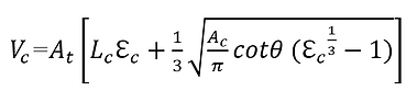
The combustion chamber is responsible for thoroughly burning the propellant mixture while containing the combustion gases. Additionally, it must be designed to prevent combustion instabilities, which can arise from local disturbances within the chamber. Maintaining stable combustion while maximizing combustion efficiency is critical. To achieve this, the combustion chamber must be large enough to ensure near-complete mixing, vaporization, and combustion of the propellants [4]. The time required for the propellants to mix, vaporize, and combust is known as the stay time or residence time. This stay time is determined by the chamber volume , propellant mass flow rate , and the average specific volume . The optimal chamber volume depends significantly on the propellant combination, as different propellants exhibit varying mixing, vaporization, and combustion characteristics [2]. The characteristic length is a parameter used to quantify the combustion chamber volume relative to the throat area .The combustion chamber volume can be calculated using Equation 3 [2].

Equation 3
Typically, as increases, combustion efficiency improves, leading to higher characteristic velocity and specific impulse Isp. However, if becomes too large, friction against the combustion chamber walls can reduce engine performance, and the required cooling capacity increases. Since the stay time depends heavily on the propellant combination, an ideal range exists for each propellant combination, as illustrated in Figure 2.
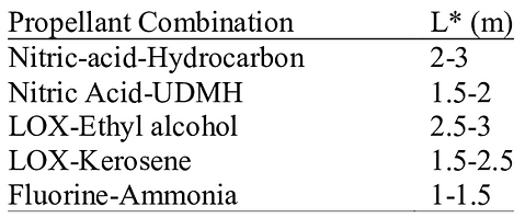
Figure 2. Characteristic lengths (L* ) for combustion chamber [3]
Based on Table 1, the range for liquid oxygen (LOX) and ethyl alcohol is 2.5 to 3.0 meters. Conversely, a recommended range for gaseous oxygen (GOX) and 70% ethyl alcohol is not sufficiently available. For this design, the selected value for the chamber volume was 1.0 meters. This value is shorter than the recommended range for similar propellant combinations.
Although a combustion chamber with a relatively small volume may result in a lower characteristic velocity and reduced engine performance, the trade-offs are acceptable. A smaller combustion chamber volume reduces manufacturing costs and requires less coolant for film cooling. These advantages largely offset the performance drawbacks of using a smaller combustion chamber.
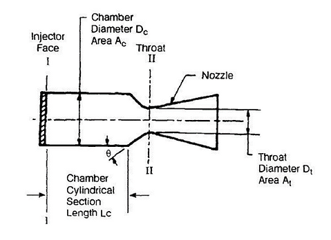
Figure 3. Elements of a Cylindrical Combustion Chamber [3]
With the combustion chamber volume determined, the combustion chamber length can be selected. As shown in Figure 3, the combustion chamber volume is defined as the space between Plane I and Plane II. The combustion chamber length is determined using a design correlation between chamber length and throat diameter, based on data from previously successful rocket engine combustion chambers. A correlation curve illustrating this relationship is provided in Figure 4. Given that the calculated throat diameter is 15.28 mm, a chamber length of 9 cm was selected. This chamber length corresponds to the distance between Plane I and Plane II.

Figure 4. Historical correlation between throat diameter and chamber length [4]
The chamber diameter that satisfies the previously calculated combustion chamber volume and chamber length is then determined. First, the contraction ratio , defined as the area ratio between the combustion chamber plane and the throat plane (as shown in Equation 4), is calculated using Equation 5 [3]. The contraction angle was arbitrarily selected as 30 degrees. The calculated contraction ratio was found to be 16. Using the previously determined throat area and contraction ratio, the chamber diameter was calculated with Equation 4 [3].

Equation 4
Equation 5
Finally, the nozzle exit area should be determined. The mach number of exhaust gas at the end of the divering section of the nozzle can be determined from the Equation 6. is the pressure of the exhaust gas at the end portion of the nozzle. Since the thrust of the rocket engine is as Equation 7, specific impulse or engine efficiency is maximized when is identical to the ambient atmospheric pressure [4]. Therefore, was determined as identical as 1 atmospheric pressure or 1 bar.

Equation 6
Equation 7
The nozzle exit area can be calculated using the isentropic Mach relation, as shown in Equation 8 [5]. This relation accounts for the flow properties of the exhaust gases and their Mach number at the nozzle exit, ensuring accurate determination of the exit area.
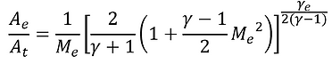
Equation 8
Lastly, the geometry of the nozzle was determined. The nozzle accelerates the hot exhaust gases from the combustion chamber to supersonic velocities, making it a critical component for the performance of the rocket engine. Conical and bell-shaped nozzles are the two most common types. Regardless of the type, nozzles consist of three sections: the converging section, throat, and diverging section. The primary difference between the two lies in the geometry of the diverging section.
A conical nozzle features a conical-shaped diverging section, whereas a bell nozzle has a bell-shaped diverging section. Conical nozzles are relatively easier to manufacture; however, their diverging sections are longer compared to those of bell nozzles, which increases their weight. In contrast, a bell nozzle typically has a shorter length—about 80% of the length of an equivalent conical nozzle—and provides approximately 1% higher efficiency. Additionally, the reduced length and weight of the bell nozzle make it advantageous for many applications. A size comparison between equivalent conical and bell nozzles is shown in Figure 5.

Figure 5. Size comparison of conical and bell nozzle [3]
Figure 6. Conical nozzle and parameter profile [6]
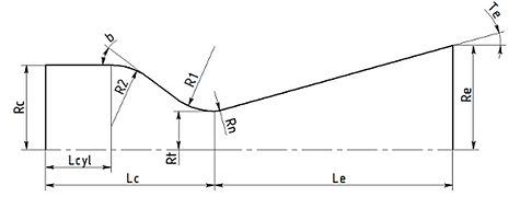
Considering easiness of manufacturing and to fulfill the goal of developing the low-cost liquid propellant rocket engine, conical nozzle with 15 degrees half angle was selected. Theoretically, a conical nozzle with a 15 degrees half angle has 98% efficiency. Elongating conical nozzle may produce slightly more axial flow of exhaust gas, but wall friction losses of long nozzle can rather decrease the engine efficiency. And most of all, the weight increases. Therefore, 15 degrees half angle is a popular option for a conical nozzle. Greater half angle than 15 degrees causes flow separation, which is detrimental to the engine’s efficiency. The calculated combustion chamber design parameters are listed in figure 7.
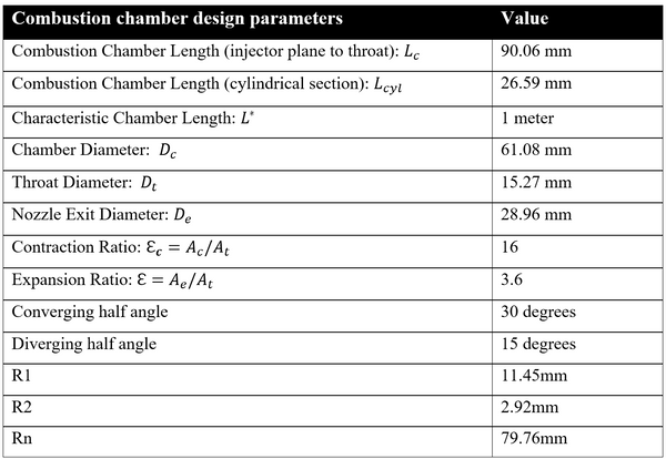
Figure 7. Combustion chamber design parameters
The combustion chamber and nozzle contour were calculated based on the parameters determined above. The contour was generated by inputting these parameters into the Rocket Propulsion Analysis (RPA) software. Figure 8 shows the resulting contour of the combustion chamber and nozzle for the 500N ethanol/GOX bi-propellant rocket engine.
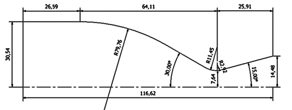
Figure 8. RPA generated combustion chamber contour [6]
2.3 Combustion Chamber Cooling
The temperature of the combustion chamber wall can reach up to 3000 K if no cooling method is applied [4]. Such extremely high temperatures and heat fluxes can melt the combustion chamber wall and lead to structural failure. At this temperature, almost all metals lose their mechanical strength. Therefore, the combustion chamber must be cooled using specialized methods designed for these extreme conditions.
Various cooling methods have been developed for rocket engine combustion chambers, including film cooling, transpiration cooling, ablative cooling, radiation cooling, dump cooling, and regenerative cooling. Among these, regenerative cooling is the most widely used method due to its effectiveness in large-scale applications. However, regenerative cooling tends to be expensive and inefficient for small combustion chambers. For this study, a combination of film cooling and ablative cooling methods was selected to address these challenges.
A. Film cooling
Film cooling is a method in which a thin layer of coolant is injected onto the combustion chamber wall, creating a protective thermal barrier between the hot combustion gases and the wall. As illustrated in Figure 9, the coolant is injected along the perimeter of the combustion chamber through injector holes. Although the coolant vaporizes into gas as it travels along the combustion chamber wall, the gaseous layer continues to provide thermal protection and effective cooling. The coolant used for film cooling can be either fuel or oxidizer, but fuel is typically the more practical option. Consequently, fuel film cooling (FFC) was selected for this design.

Figure 9. Diagram of a film cooling method
To design the film cooling system, the ratio of the film coolant mass flow rate to the total injected fuel mass flow rate must be determined, as shown in Equation 9 [7]. For this design, a value of 0.1 was chosen. Figure 10 illustrates the heat flux distribution, while Figure 11 shows the temperature distribution after applying film cooling.
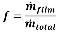

Equation 9
Figure 10.
Figure 11.
According to Figure 11, the temperature distribution along the cylindrical section of the combustion chamber remains below 1800 K, which is the melting point of stainless steel 304. Therefore, it can be concluded that the fuel film cooling method is sufficient for cooling the cylindrical section of the combustion chamber, which is constructed from stainless steel 304. However, in the nozzle section, the temperature reaches up to 2300 K, exceeding the melting point of stainless steel 304. This issue will be addressed in detail in the following section.
B. Ablative cooling
The ablative cooling method was selected for cooling the nozzle section of the engine. Ablative cooling involves the use of a specialized liner material that vaporizes at a constant rate, forming a protective gas boundary to shield the combustion chamber wall from the hot combustion gases. This method is highly sensitive to combustion chamber pressure; as the chamber pressure increases, the ablation rate also rises, potentially making the method unsuitable. However, for engines with low combustion chamber pressure, like this one, ablative cooling is an excellent option due to its cost-effectiveness and simplicity of manufacturing.
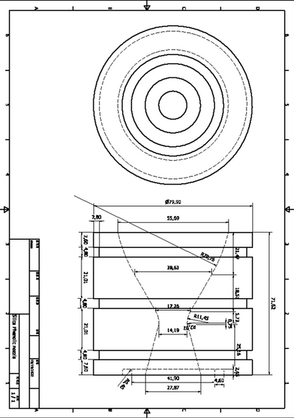
Common materials used for ablative cooling include carbon-phenolic, carbon-carbon, graphite, and silica-phenolic composites [3]. Among these, silica-phenolic was chosen for its affordability and proven reliability. Figure 12 illustrates the silica-phenolic composite cooling method. Figure 13 provides a summary of the cooling methods used in this design: film cooling for the cylindrical section and ablative cooling for the nozzle section.

Figure 12. Silica Phenolic composite

Figure 13. Combustion chamber cooling
Figure 14. Combustion chamber components
Figure 15. Silica phenolic nozzle
2.4 Injector & Manifold
A. Pintle Injector
The injector of a bipropellant liquid rocket engine is a critical component directly tied to the engine's performance. Its primary role is to atomize and mix the propellants in the combustion chamber, promoting steady and near-complete combustion. There are various types of injectors, each with unique advantages and disadvantages. While the injector is responsible for introducing propellants into the combustion chamber, the manifold guides the propellants from their respective feedlines to the injector. The manifold must be designed to ensure uniform distribution of propellants to the injector orifices while minimizing pressure losses.
These factors were carefully considered during the injector design. As previously mentioned, a pintle injector was selected for this engine. Although coaxial swirl injectors—currently the most widely used injectors in launch vehicle engines—offer superior mixing and atomization capabilities, they are complex and expensive to manufacture. Additionally, coaxial swirl injectors rely on a series of separate propellant injection orifices distributed across the combustion chamber's headend, further complicating their design [1].
In contrast, the pintle injector offers a simpler and more cost-effective alternative. Unlike other injector types, the pintle injector employs a central, singular injector element, which significantly reduces manufacturing costs. Despite its simplicity, the pintle injector delivers high combustion efficiency (96%-99%) and supports unique operating features such as deep throttling and injector face shutoff [1]. The general dimensions of the pintle injector are shown in Figure 16.

Figure 16. Concept of pintle injector [1]
There are three parameters that determines the geometry of the pintle injector. The geometry is shown in Figure 17. The parameters ratio of chamber to pintle diameters , skip distance , and blockage factor BF. The recommended ratio of chamber to pintle diameter is 3 to 5. Since the chamber diameter is determined as 60mm in the previous chapter, the pintle diameter of 15mm was chosen, with the chamber to pintle ratio of 4. [8]. The skip distance, the length of the annular flow passage is determined by the ratio of skip distance to pintle diameter . The recommended value for this ratio is 1. Previous empirical results showed that combustion efficiency decreased when skip distance was greater or less than 1. When the skip distance equaled 1, combustion efficiency was the highest [9]. Therefore, the default skip distance was set to 1, and was determined to be 15 mm to the pintle diameter. The last parameter, the blockage factor BF, is defined as the ratio of the circumferential length of the holes or slot at the end of the pintle to the pintle circumference. 𝐵𝐹 is shown by Equation 10, where and are number of radial flow holes and circumferential length of each hole respectively. The recommended value for BF is 0.3~1 [10]. Figure 18 shows the dimension of the multi-hole pintle injector tip.
Figure 17. Pintle injector dimension [8]
Equation 10
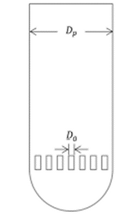
Figure 18. Multi-hole type pintle geometry [11]
Since there are regions where annular flow and radial flow don’t collide when BF is less than 1, the optimum value for blockage factor is 1. The blockage factor of less than 1 result a reduction in mixing and atomization efficiency. Plus, as BF decrease, the characteristic velocity decreased. [12]. Therefore, the pintle injector should be designed in a way in which the value of BF is maximized. However, in small rocket engines, since mass flow rate of propellants is relatively small, it is difficult to keep the BF as high as 1. In this research, considering its relatively small combustion chamber and mass flow rate of propellants, BF value of 0.3 was selected.
The injector orifice area can be determined using Equation 11 [3] where A is area, is discharge coefficient, is pressure drop across the injector orifice, and is density of the fluid. Firstly, the mass flow rate should be determined in prior to the calculation of the injector orifice area A. Mass flow rate of the engine can be found using Equation 12, where is combustion chamber pressure, is combustion chamber temperature, is gas constant, and is specific heat ratio [2]. The specific heat ratio and combustion chamber temperature was calculated using CEA as aforementioned. The mass flow rates of each fuel and oxidizer were calculated as 0.12010 kg/s and 0.12010 kg/s respectively. Mass flow rate of each propellant are identical since O/F ratio is 1.
Equation 11

Equation 12
The recommended value for the pressure drop across the injector orifice is 15 ~20 percent of combustion chamber pressure [modern engineering for liquid propellant rocket engine]. However, in small scale engines, higher pressure drop is recommended to prevent the chugging instability. Considering the size of the engine, the pressure drop value of 25% was selected. Since the combustion chamber pressure of 20 bar was selected, the pressure drop is 5 bar. Discharge coefficient is typically determined experimentally. For annular flow orifice, discharge coefficient value of 0.8 was selected. Following the experimental value obtained from the previous studies, for the radial flow passage discharge coefficient was determined to be 0.6 [10]. Having determined discharge coefficient , pressure drop , mass flow rate , and injector orifice area A can be calculated. The result of calculation is shown in figure 19.
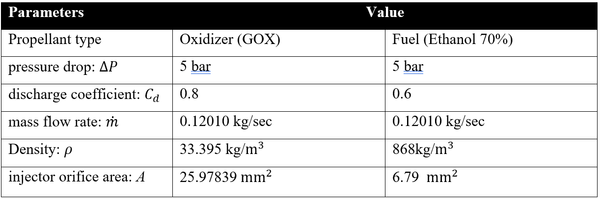
Figure 19.
As the final step, the propellant type for annular flow and radial flow injector should be determined. Fuel (ethanol) was chosen for the radial flow because the pintle has to be regeneratively cooled from the hot combustion gas. GOX is not applicable because gaseous propellant provides inferior cooling performance compared to the liquid propellant. As a result, oxidizer (GOX) was selected for the annular flow. Using equation 13, value of 19 was selected and diameter of radial flow holes value of 0.6mm was selected. Finally, using Equation 14, diameter for the annular flow passage was calculated as 16.065mm.

Equation 13

Equation 14
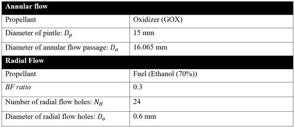
Figure 20.
Copper was selected as the material for the pintle. 1.5mm thin copper wall act as a regenerative cooling wall and protect the pintle from melting while being directly exposed to hot combustion gas. Figure 21 illustrate the final pintle injector design.

Figure 21. Pintle injector
B. Film cooling injector
For simplicity in design pressure drop , and the propellant type was chosen exactly same as the fuel injector above. Mass flow rate is 10% of total mass flow rate, which is 0.024020 kg/sec. The Injector orifice area A was calculated using equation 11. Uniform flow of film coolant is necessary for high cooling efficiency. Therefore, hole diameter of 0.3mm, which is practically smallest machinable diameter for stainless steel material. The number of holes of 15 was calculated accordingly. Figure 22 shows the parameters for the film cooling injector. As shown in Figure 23, a hole was drilled with 10 degrees inclination for higher cooling efficiency.
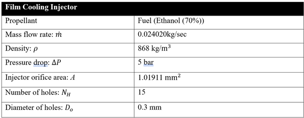
Figure 22.
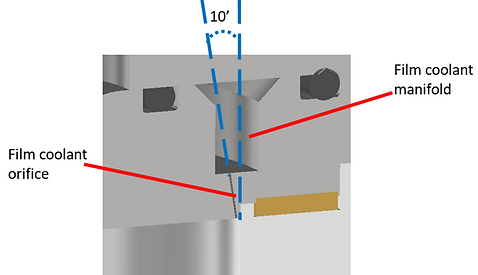
Figure 23.
C. Manifold
A manifold system is responsible for even distribution of propellants to the designated injector orifices. The cross section of manifold is shown in Figure 24. The manifold must channel propellant evenly to the injector faces with minimal pressure losses [3]. Since, the oxidizer (GOX) has a low density and large volume, oxidizer manifold is designed to have a large volume to minimize the pressure loss because. The pintle itself is designed to function as both injector and guideline manifold. Manifold for the film cooling coolant is designed in one piece with the oxidizer manifold. Also, manifold must function as a heat shield from the hot gas, so the propellants don’t boil. Therefore, the injector face, which is in the direct contact with the hot combustion gas, is designed to be 1.5 cm thick. The injector and manifold compartment are composed of 4 components: Figure 25, Figure 26, Figure 27, and Figure 28.

Figure 24. Cross sectional view of manifold and injector

Figure 25. Fuel inlet

Figure 26. Pintle

Figure 27. Oxidizer manifold

Figure 28. Injector face
2.5 Ignitor
The ignitor is a component which is responsible for the ignition of propellants in the combustion chamber. If ignition is delayed, the rocket engine is likely to experience hard start, leading to the damage and increase on the risk of explosion of the engine [2]. Therefore, during the ignition sequence of the engine, the ignitor must provide higher than auto ignition temperature while propellants are being injected into the combustion chamber [2].
The system selected for the engine is the spark initiated torch ignitor for its reliability. The torch ignitor which uses ethanol 70% and GOX was designed. For the simplicity during integrated test with the main combustion chamber, the propellant combination, pressure drop across the injector orifice, and the combustion chamber pressure was designed to be identical with that of the main combustion chamber. For the O/F ratio, optimum value of 1.3 was selected to provide sufficient heat while ignition. The value was gained from NASA’s Chemical Equilibrium Analysis. Figure 29 summarizes the ignitors operating factors.
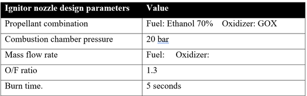
Figure 29. Torch ignitor operating conditions
The combustion chamber and nozzle for the spark initiated torch ignitor was designed by the method described in detail above. The contraction ratio of 16 and characteristic length of 1 meter was selected for the combustion chamber. For the nozzle, conical nozzle with 15 degrees half angle was selected. Figure 30 shows the parameters for the nozzle geometry and Figure 31 shows the finalized combustion chamber and nozzle geometry of the torch ignitor.
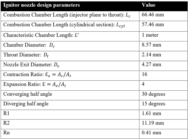
Figure 30. Torch ignitor combustion chamber design factors

Figure 31. Torch ignitor chamber geometry
The torch ignitor is designed to adapt passive cooling method. The ignitor body is designed with a large thermal mass so the body itself can function as a heat sink from the hot combustion gas. Stainless Steel 304 was selected for the body material. The Ignitor body has a 3 port. Each port is designated for the spark plug, oxidizer inlet, and fuel inlet as shown in figure 32. For the oxidizer inlet side, the oxidizer orifice plate was added to act as the oxidizer injector orifice and bulk head at the same time. By adapting this design method, the injector body can be manufactured in one-piece. This unique design enabled to delete bulky flanges for connecting injector body parts. CM6 spark plug was selected for its superior availability. BSPP fitting was selected to be connected with the injector body, and oxygen-free, high conductivity (OFHC) copper gasket was selected as the sealing between fittings and the injector body. Figure 33 shows the illustration of the torch ignitor.

Figure 32. Torch ignitor cross section

Figure 33. Illustration of the torch ignitor
The ignitor is designed to be mounted onto the main combustion chamber as shown in figure 34, oxygen-free, high conductivity (OFHC) copper gasket is selected as a sealing between the ignitor body and the combustion chamber wall. Figure 35 shows the components of the ignitor.

Figure 34. Torch ignitor mounted on the combustion chamber

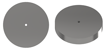
Figure 35. Torch ignitor components
2.6 Measurement
Among the various data obtained from the hot-fire test of the engine prototype, chamber pressure is the most critical. Measurements of combustion chamber pressure during testing enable the derivation of key combustion parameters, such as characteristic velocity and thrust coefficient. However, obtaining accurate pressure measurements is challenging due to the extreme temperatures and pressures within the combustion chamber. Direct measurement methods often require structural modifications to the propulsion system, rendering it unusable for further testing. To address these challenges, the pressure measurement system was designed to be non-invasive to the internal combustion reaction [13].
The selected measurement method utilizes a pressure transducer, which converts pressure into an electrical signal. Pressure transducers are capable of measuring a wide range of pressures, often up to hundreds of bars. However, the extreme heat within the combustion chamber would destroy a transducer in seconds if it were directly mounted to the chamber wall. To overcome this limitation, an alternative approach was adopted: distancing the pressure transducer from the combustion chamber.
A pressure transducer tubing system was implemented to address this issue. The tubing connects the combustion chamber to the transducer, accurately transmitting pressure as if the transducer were directly attached. A ¼-inch male BSPP fitting was selected to connect the tubing to the combustion chamber body. To ensure a reliable seal under extreme conditions, an OFHC copper gasket was used at the connection point. A perpendicular hole was drilled into the combustion chamber wall to accommodate the fitting. To minimize the risk of burn-through, a small diameter of 1 mm was selected for the hole, and its length was set at 5 mm. The relatively long, cylindrical hole is expected to act as a heat sink, reducing the risk of melting the stainless steel wall due to the high combustion gas temperatures. Figure 36 illustrates the measurement port design on the combustion chamber wall.

(a)

(b)
Figure 36. Combustion chamber with pressure transducer tubing attached
ASSEMBLY
3.1 Connections
The injectors, manifolds, and combustion chamber components were all designed with flanged bolt connections. This connection method was selected for its reliability, simplicity, and low machining cost. Flanged connections also accommodate the tolerance changes caused by the OFHC copper gasket and allow for rapid disassembly and reassembly as needed.
The upper manifold and injector components were secured with eight M8-70 mm stainless steel bolts and nuts, as shown in Figure 37. To prevent loosening, M8 washers were placed on both sides of the flange, totaling 16 washers. Additionally, a 5 mm-thick stainless steel 304 plate was added to hold the silica-phenolic ablative cooling nozzles in place. This plate was bolted to the combustion chamber body using eight M8 bolts and nuts. The designed silica-phenolic nozzle holder is illustrated in Figure 38.

Figure 37. Cross section of the engine
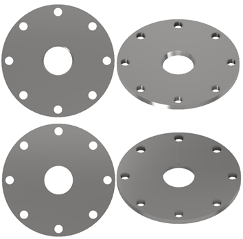
Figure 38. Silica Phenolic Nozzle Retainer
3.2 Sealing
For sealing, O-rings and Oxygen-Free High Conductivity (OFHC) copper gaskets were utilized. Copper gaskets were employed for connections in direct contact with hot combustion gases, while O-rings were used for connections exposed to propellants but not in direct contact with combustion gases. Viton O-rings were selected due to their excellent chemical resistance and high-temperature tolerance. Figure 39 illustrates the sealing methods used.
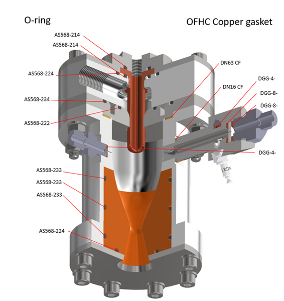
Figure 39. O-ring & OFHC copper gasket
REFERENCE
[1] Dressler, G. A., Bauer, J. M., TRW pintle engine heritage and performance characteristics, 36th AIAA/ASME/SAE/ASEE Joint Propulsion Conference & Exhibit, Huntsville, AL, 2000.
[2] Sutton, G. P., Biblarz, O., Rocket Propulsion Elements. Wiley and Sons, 7th edition, 2001.
[3] Huzel, D. K., and Huang, D. H., Modern Engineering for Design of Liquid-Propellant Rocket Engines, Washington DC: American Institute of Aeronautics and Astronautics, 1992.
[4] Braeunig, R. A., “Rocket Propulsion,” Rocket & Space Technology, retrieved 25 April 2020. http://www.braeunig.us/space/index.htm
[5] Anderson, J. D., Modern Compressible Flow: With Historical Perspective, 3rd ed., McGraw-Hill Education, New York, 2002.]
[6] Rocket Propulsion Analysis https://www.rocket-propulsion.com/index.htm
[7] McCall, Jonathan Floyd. Discrete Film Cooling in a Rocket with Curved Walls. ENY, Air Force Institute of Technology. 2009.
[8] Heister, S. D., Handbook of Atomization and Sprays, Springer, New York, 2011.
[9] Fang, X., Shen, C., Study on atomization and combustion characteristics of LOX/methane pintle injectors, Acta Astronaut. 136 (2017) 369-379
[10] Yoon, Y., Koh, H., Kim, D., Khil, T., Spray visualization using laser diagnostics, J. Korean Society of Visualization, 3 (2) (2005) 3-13
[11] Lee, S., Koo, J., Yoon, Y., Technology and developing trends of pintle injector for throttleable engine, J. Kor. Soc. Propuls. Eng., 21 (4) (2017) 107-118.
[12] Yu, K., Son, M., Koo, J., Effects of opening distance on liquid-gas spray of pintle 88 injector under atmospheric condition, J. Korean Soc. Aeronaut. Space Sci., 4. (7) (2015) 585-592.
[13] H. Flaherty and N. O’Neill, “Design of minimally invasive method for combustion chamber pressure measurements in HTPB/N2O hybrid rocket motors,” https://www.colorado.edu/aerospace/sites/default/files/ attached-files/hickam_aiaa.pdf
APPENDIX A


APPENDIX B
