A Development of Autonomous Propellant Harvesting Hopper (APHH)
Wanglim Song
ABSTRACT
This paper introduces the Autonomous Propellant Harvesting Hopper (APHH), a rocket-propelled device that employs a novel propulsion system to process surface ice as propellant. The APHH autonomously collects ice, filters out impurities, and generates thrust using four cold gas thrusters. This innovative approach enables continuous exploration of icy extraterrestrial bodies, provided a reliable electricity source. Potential applications include exploration of celestial bodies with ice-dominated crusts, such as Uranus, Neptune, Pluto, and Europa. The paper details the design, assembly, and testing processes of the APHH.
CONTENTS
-
INTRODUCTION
-
Research motivation
-
Research summary
-
-
SYSTEM CONCEPT
-
Design concept
-
2.2 Propulsion type selection
2.3 Propellant selection
2.4 Propellant Harvesting & Processing
2.5 Preliminary system design
-
HARDWARE DESIGN
-
Cold Gas Thruster
-
Liquefaction Tank
-
Heating Tank
-
Harvesting Robot Arm & Hand
-
Frame
-
Valve
-
Assembly
-
-
TESTING
-
Cryogenic Test
-
Static Fire
-
-
CONCLUSION
-
Conclusion
-
-
REFRENCE
1. INTRODUCTION
1.1 Research motivation
Various methods are employed to explore extraterrestrial bodies, including Mars, dwarf planets, and asteroids. Among these, the use of rovers is the most prevalent. For example, on Mars, where the surface is predominantly rocky, rovers are a practical and efficient exploration tool. In 2021, however, NASA introduced a new approach by deploying the drone Ingenuity to explore Mars. Drones offer the advantage of covering much larger areas than rovers and can access terrains that are inaccessible to rovers. Conventional drones, however, generate lift by pushing air downward using devices like propellers, which makes them impractical for exploring celestial bodies with little to no atmosphere.
Interestingly, many dwarf planets, such as Pluto, and moons, such as Europa, have crusts composed of ice. This observation suggests that a drone, or "hopper," capable of using surface ice as propellant could significantly expand the exploration range beyond what rovers or stationary probes can achieve. Therefore, the goal of this study is to develop the Autonomous Propellant Harvesting Hopper (APHH), which utilizes an innovative propulsion system that processes surface ice as propellant.
1.2 Research summary
In this study, the Autonomous Propellant Harvesting Hopper (APHH), which utilizes solid carbon dioxide (dry ice) as a propellant, was developed. Since the environmental conditions of dwarf planets and asteroids differ significantly from those on Earth, it is challenging to fully simulate these extraterrestrial environments on Earth. Consequently, the APHH was designed with Earth's physical conditions in mind.
The APHH consists of two main systems: a harvesting system and a propulsion system. The harvesting system includes a grinding mechanism and a robotic arm for collecting and transferring ice. To minimize energy consumption, the grinder employs a claw-shaped shovel actuated by a single servo motor to grind the surface and collect fragments of ice. The collected fragments are then lifted 70 cm using a servo-actuated robotic arm and conveyed into a liquefaction tank.
The propulsion system operates in three steps: (1) liquefaction of solid carbon dioxide, (2) heating the liquefied carbon dioxide, and (3) expelling the supercritical carbon dioxide through thrusters. Initially, the crushed dry ice enters the 4.5-liter liquefaction tank, constructed from lightweight aluminum 6061 alloy to withstand pressures up to 180 bar. Upon entering, the dry ice begins to vaporize as carbon dioxide cannot remain solid at room temperature. When the pressure exceeds 5 bar, the dry ice transitions to a liquid state. Once liquefied, the carbon dioxide is filtered through activated carbon pellets to remove impurities. The purified liquid carbon dioxide is then transferred to a heating tank, where it is heated to over 40°C, generating a pressure of 100 bar and converting it into a supercritical state. A pressure regulator reduces the pressure to 20 bar before the supercritical carbon dioxide is expelled through cold gas thrusters, each generating 50 N of thrust.
Testing of the APHH was conducted on a surface densely covered with dry ice to simulate the conditions of an ice-covered planetary surface. The dry ice collection system successfully delivered a sufficient quantity of material to the liquefaction tank, which effectively liquefied the dry ice and filtered out impurities. However, due to cold weather conditions during testing, the generation of supercritical carbon dioxide was unsuccessful, and sufficient thrust for lifting the APHH was not achieved.
Future research will focus on enhancing the APHH's performance. Flight duration will be tripled by reducing the weight of the hardware components. Additionally, four adjustable valves will be incorporated to independently control the thrust of each thruster, addressing safety limitations encountered in this study. The current APHH has a short flight duration due to being optimized for Earth's gravity. However, in environments with lower gravity, such as the polar regions of Mars, the APHH is projected to achieve a flight time of 50 seconds. On Europa, where gravity is even lower, the flight time could extend to approximately three minutes. These advancements could significantly expand the potential for extraterrestrial exploration.
2. System Concept
2.1 Design concept
To overcome the limitations of conventional extra-terrestrial exploration methods which involve rovers and etc., the APHH was designed and developed to meet the following objectives.
-
Propellant harvesting from the surface of extra-terrestrial body.
-
Processing of harvested propellant.
-
Propulsion system that supports multiple firing.
-
All-In-One Design.
2.2 Propulsion type selection
The propulsion system, as previously mentioned, must be durable and reusable for multiple operations. Therefore, a system with a simple and robust design was selected to ensure reliability over numerous startups and extended operation periods. Additionally, since the APHH is intended for the exploration of extraterrestrial bodies, the propellant used must be easily obtainable on these surfaces. To satisfy these requirements, a cold gas propulsion system was chosen as the propulsion method.
A cold gas propulsion system is a type of rocket propulsion that generates thrust using pressurized gas. Unlike other propulsion systems, a cold gas system does not rely on chemical reactions such as combustion or catalytic processes. Instead, thrust is produced solely through the expansion and acceleration of pressurized gas. While the absence of chemical reactions simplifies the design and enhances reliability, it also results in a lower specific impulse (Isp) and efficiency compared to other propulsion types.
Figure 1 illustrates the concept of a cold gas propulsion system. This system offers several notable advantages:
-
Simple and light weight design.
-
Limitless operation time.
-
Safety
-
Simplicity

Figure 1. A concept of a cold gas propulsion system [3]
2.3 Propellant selection
When determining the appropriate propellant for a cold gas propulsion system, factors such as density, toxicity, and specific impulse (Isp) must be carefully considered [1]. A cold gas propulsion system can utilize either liquid or gaseous propellants, as the propellant’s state is irrelevant as long as it exits the nozzle in a gaseous form. However, if all other factors are identical, selecting a liquid propellant is generally preferred due to its lower storage volume requirements.
In addition to state and density, the reactivity and availability of the propellant are critical considerations during the selection process. For safety and operational simplicity, using an inert or low-reactivity propellant is highly recommended [8]. Furthermore, the specific impulse (Isp) of the propellant is a key performance metric. A higher Isp is advantageous as it results in longer flight durations and reduced propellant mass requirements, making the selection of a high-Isp propellant preferable [2].
Figure 2 illustrates the specific impulses of various propellant types for cold gas propulsion systems, highlighting their relative efficiencies and potential applications.
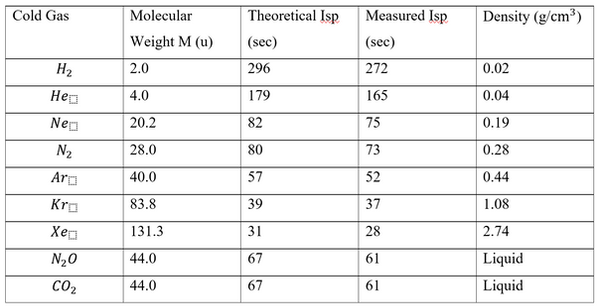
Figure 2. Propellants and efficiency for cold gas propulsion system at C and 241 bar [4]
Carbon dioxide (CO₂) was chosen as the propellant for the cold gas propulsion system in the APHH. This selection was primarily based on its reliability and accessibility. Carbon dioxide is a proven propellant that has been widely used in small satellite cold gas propulsion systems [13]. Additionally, it is a relatively non-toxic substance, posing no significant harm to humans when exposed in small quantities.
One of the key advantages of using carbon dioxide is its availability in solid form as dry ice. By utilizing dry ice as the propellant, the otherwise complex and energy-intensive propellant solidification process can be bypassed during experiments. These combined benefits—reliability, safety, and ease of procurement—make carbon dioxide an ideal choice for the APHH's propulsion system.
2.4 Propellant Harvesting & Processing
A. Harvesting
The initial step in the process involves harvesting ice, the raw material for the propellant, from the surface. The harvesting system comprises a pair of grinding and scooping hands, along with a robotic arm designed to collect and lift the ice. To optimize energy efficiency, a grinding mechanism is implemented, as the propellant is in a solid state.
The grinding and scooping hands, driven by a single servo motor, grind the surface and collect fragments of ice. These fragments are then lifted 70 cm by a servo-actuated robotic arm and deposited into the liquefaction tank for subsequent processing.
B. Processing
When the harvested raw propellant is conveyed to the processing section, it is likely to contain significant impurities. If these impurities are not removed during the processing stage, contaminants such as rock fragments and dirt could damage the propellant feed lines and the cold gas propulsion system. Even fine particles of dirt can cause wear or malfunction in sensitive components, such as the pressure regulator and solenoid valve. Therefore, it is critical to remove all impurities from the raw solid carbon dioxide during processing.
Once the impurities are removed, the physical state of the propellant must be modified into a viable form for use in cold gas thrusters. This includes converting the propellant into either a gaseous or supercritical state. Since no additional heating components are included for each cold gas thruster, the purified carbon dioxide must be preheated to achieve these states, making a heating section an essential component of the system. Figure 3 shows the steps of the propellant harvesting and processing system in the APHH.

Figure 3. Steps of propellant harvesting and processing
To filter raw solid carbon dioxide (dry ice) into pure carbon dioxide, several steps are required. Before selecting an appropriate filtration mechanism, the type of mixture must be identified. Since the mixture of carbon dioxide with rock fragments and dirt is unevenly distributed, it is classified as a heterogeneous mixture [7]. Heterogeneous mixtures can be purified using solely physical methods. In this experiment, the difference in melting points of the substances was utilized to separate impurities from the raw solid carbon dioxide. The filtration process involves two main steps:
-
Liquefaction of solid carbon dioxide into its liquid state.
-
Filtration of the liquid carbon dioxide through a specialized filter to remove impurities.
Once the carbon dioxide is filtered and purified, it must be heated to a gaseous or supercritical state for use as a propellant in the cold gas thrusters. For this study, the supercritical state was chosen due to its higher density compared to the gaseous state. The increased density reduces the required volume and weight of the propellant tank, allowing a greater quantity of propellant to be stored in the hopper. This, in turn, enhances the overall flight time of the APHH. Figure 4 illustrates the pressure-temperature phase diagram of carbon dioxide, highlighting the transition to the supercritical state.

Figure 4. Carbon dioxide pressure-temperature phase diagram [5]
2.5 Preliminary system design
As previously mentioned, the APHH consists of three main subsystems: the harvesting system, the processing system, and the propulsion system. To achieve the mission objectives, the APHH was designed using an All-In-One Design concept, integrating all three subsystems into a single cohesive unit.
The first step in the design process involved drafting the Process and Instrumentation Diagram (P&ID) for the processing and propulsion systems. When developing the P&ID, it was essential to strike a balance between safety and simplicity. Since the APHH is a flight instrument, minimizing weight was a critical design consideration. Consequently, only essential components were included in the design, and non-critical safety features such as burst disks and relief valves were excluded to reduce weight.
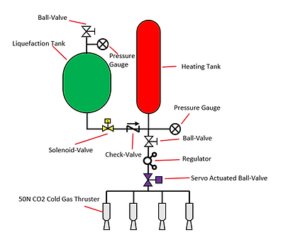
Figure 5. P&ID diagram of propulsion system for APHH
The processing and propulsion system is depicted in Figure 5. The processing system primarily consists of a liquefaction tank and a heating tank, while the propulsion system includes four 50 N cold gas thrusters.
At the upper dome of the liquefaction tank, a ball valve is installed to allow the entry of raw solid carbon dioxide. Additionally, a pressure gauge is attached to monitor the pressure within the liquefaction tank. Between the liquefaction tank and the heating tank, a solenoid valve is positioned to regulate the flow of purified liquid carbon dioxide into the heating tank. To prevent backflow from the heating tank into the liquefaction tank, a check valve is incorporated, as the pressure in the heating tank increases significantly during the heating process. Another pressure gauge is connected to the heating tank for pressure monitoring.
At the outlet of the heating tank, a manual ball valve is installed to control the release of supercritical carbon dioxide. A manual ball valve was chosen instead of a solenoid valve due to the high pressure of supercritical carbon dioxide, which exceeds the operating limits of most commercial solenoid valves. Downstream of the heating tank, a pressure regulator is installed to reduce the pressure to a manageable level. Finally, a custom-designed servo-actuated ball valve is located between the pressure regulator and the cold gas thrusters to control thrust.
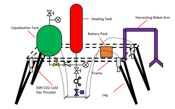
Figure 6. Concept of APHH
The harvesting system is integrated with the processing and propulsion systems to form a cohesive unit. As shown in Figure 6, the harvesting robotic arm is mounted on the side of the APHH hopper. This robotic arm grinds, scoops, and conveys solid carbon dioxide fragments to the inlet of the liquefaction tank. Within the processing system, a battery pack is included to supply electricity for heating the liquid carbon dioxide. The liquefaction tank and heating tank are securely mounted onto the hopper’s frame, which is supported by attached legs for structural stability.
Before designing individual components, key parameters that influence the size and flight time of the APHH were determined. These design parameters include the thrust of the cold gas propulsion system F and the propellant mass . It was established that, utilizing commercially available COPV (Composite Overwrapped Pressure Vessel) and other valve components, the total mass of the APHH, including the propellant, must not exceed 15 kg. Based on this constraint, a net thrust of 200 N was chosen for the APHH. The propellant mass was then determined according to the volume of the selected COPV tank. With a COPV tank volume of 3 L, the propellant mass was calculated to be 2 kg.
Given a total thrust of 200 N and a propellant mass of 3 L, the expected flight time can be calculated. The specific impulse for a cold gas thruster using carbon dioxide as a propellant is approximately 60 seconds, and the standard gravity is 9.8 m/s². The mass flow rate is calculated using Equation 1 and found to be 0.34 kg/s.
Assuming ideal conditions—where air resistance is negligible, external net force is zero, and the thrust-to-weight ratio (TWR, Equation 3) is 1—the flight time t can be determined by dividing the propellant mass by the mass flow rate, as shown in Equation 2. The expected flight time is 5.88 seconds. Figure 7 summarizes the calculated initial parameters and factors.
Equation 1

Equation 2

Equation 3

Figure 7. APHH initial parameters.
3.Hardware Design
3.1 Cold Gas Thruster
The cold gas thruster converts potential energy (high pressure) into kinetic energy, producing thrust. The APHH incorporates four identical cold gas thruster assemblies, each generating 50 N of thrust to achieve a total thrust of 200 N. The cold gas thruster primarily consists of a nozzle that expands and accelerates carbon dioxide from high inlet pressure to low pressure and supersonic speed. Thus, the nozzle geometry is critical for achieving the desired performance.
Before designing the nozzle geometry, the inlet pressure must be determined. For the APHH, an inlet pressure of 20 bar was selected based on the chosen specifications of the pressure regulator. The thrust coefficient was calculated using Equation 4, where γ is the specific heat ratio (1.40 for carbon dioxide at 20 bar), is the throat area, is the nozzle exit area, is the inlet pressure, is the nozzle exit pressure, and is the atmospheric pressure (1 atm) [2].
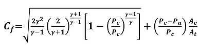
Equation 4
After calculating the thrust coefficient , the throat area can be determined. Using Equation 5, thrust F is expressed as shown in Equation 6 [1]. By inputting the previously determined parameters, the throat area is calculated as 16.47 mm² using Equation 6 [9].
Equation 5

Equation 6
Finally, the nozzle exit area must be determined. represents the pressure of the exhaust gas at the nozzle's exit. As described in Equation 7, the specific impulse and engine efficiency are maximized when equals , the ambient atmospheric pressure [10]. Thus, was set to 1 atmospheric pressure (1 bar). Using Equation 8 [9], the nozzle exit area was calculated as 47.585 mm².
Equation 7

Equation 8
Lastly, the geometry of the nozzle was determined. Conical and bell-shaped nozzles are two common types, both consisting of three sections: the converging section, throat, and diverging section. The key difference between these types lies in the shape of the diverging section, as illustrated in Figure 8. A conical nozzle features a conical diverging section, while a bell nozzle has a bell-shaped diverging section.
For the APHH, a conical nozzle with a 15-degree half-angle was selected due to its simplicity and ease of manufacturability. Using the calculated throat area and exit area, the nozzle throat diameter and exit diameter were determined. Figure 9 presents the calculated values for the cold gas thruster.

Figure 8. Comparison of conical and bell nozzle [1]
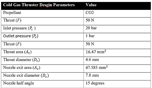
Figure 9. Design parameters for the cold gas thruster

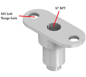
Figure 10. Illustration of a 50N Cold gas thruster
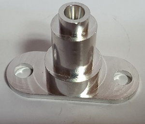

Figure 11. 50N Cold gas thruster
3.2 Liquefaction Tank
The liquefaction tank is responsible for both liquefying and filtering raw solid carbon dioxide. It liquefies solid carbon dioxide and removes impurities such as rock fragments and dirt. The filtration process consists of two main steps: (1) liquefaction of solid carbon dioxide into a liquid state, and (2) filtration of the liquid carbon dioxide through a filter bed.
The tank was designed with a hemispherical shape, as shown in Figure 12, to minimize stress concentration. The filter bed is positioned in the cylindrical section, which divides the tank into two halves.

Figure 12. Concept of the Liquefaction tank
To design the liquefaction tank, the operating pressure must be determined. When solid carbon dioxide is contained in a closed system at room temperature, it vaporizes due to the high temperature. However, not all solid carbon dioxide transitions to the gaseous state. Once the pressure reaches the vapor pressure (or equilibrium vapor pressure), the vaporized carbon dioxide becomes saturated and begins to liquefy.
Thus, the operating pressure of the liquefaction tank is equal to the vapor pressure of carbon dioxide at the operating temperature. According to Figure 13, the vapor pressure of carbon dioxide is 55 bar at 290 K. Therefore, the operating pressure of the liquefaction tank was set to 55 bar.

Figure 13. Vapor pressure of Carbon dioxide [11]
The size of the liquefaction tank was determined as the second step in the design process. The tank must be capable of liquefying the full 2 kg of solid carbon dioxide (the propellant mass) in a single process. Given the density of solid carbon dioxide (1.6 g/ml), the volume of 2 kg is calculated to be 1.25 liters. Including a 35% margin, the volume of each hemispherical section of the tank was set to 2 liters.
Using Equation 9, the tank diameter was calculated to be 20 cm. The length of the cylindrical section, which accommodates the filter bed, was set to 4 cm.
Equation 9
The liquefaction tank must be designed to withstand pressures exceeding 55 bar to ensure safety. A one-dimensional analysis method was employed to calculate the required thickness of the pressure vessel. Both circumferential and longitudinal stresses were considered in the analysis. The hemispherical section was treated as a thin-walled pressure vessel, as defined by Equation 10.

Equation 10
To determine the stress in the hemispherical vessel, the sphere was cut in half along its vertical diameter, as shown in Figure 15. The tensile strength σ and the pressure P are illustrated in the figure. The longitudinal forces acting on the vessel are uniformly distributed along the circular plane, resulting in the pressure force described in Equation 11.

Figure 15
Equation 11
Since the force is uniformly distributed along the circular perimeter of the pressure vessel which has a thick ness of t, equilibrium of forces in the hemispherical pressure vessel is described as Equation 12.
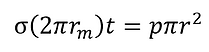
Equation 12
Lastly, the thickness of the hemispherical pressure vessel can be calculated using Equation 13, where p is the internal pressure, r is the radius of the pressure vessel, σ is the tensile strength of the tank material, and SF is the safety factor.
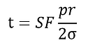
Equation 13
The thickness of the cylindrical section of the pressure vessel is calculated differently from that of the hemispherical section. Unlike the hemispherical vessel, the cylindrical pressure vessel is subjected to both longitudinal and circumferential stresses. To analyze these stresses, the cylinder was sectioned horizontally along the x and y axes, as shown in Figure 15.
As illustrated, the cylindrical pressure vessel experiences two different tensile stresses ( and ). The pressure acting on the vessel is uniformly distributed along the circular plane, resulting in the pressure force described by Equation 11. The circumferential stress is defined by Equation 14.
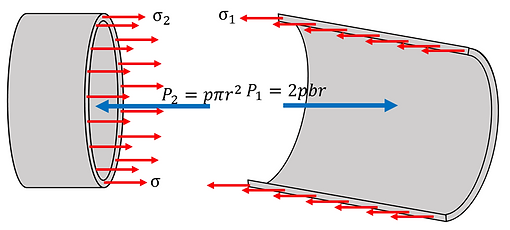
Figure 16
Equation 14
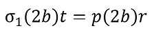
The circumferential force acts uniformly along the cylinder’s wall, resulting in an equilibrium between the pressure force and the tensile strength of the cylinder, as described by Equation 15.

Equation 15
In addition to the circumferential force, the longitudinal force—identical to that in the hemispherical pressure vessel—also acts on the cylindrical pressure vessel. However, as shown in Equation 16, the circumferential force is the governing force in this system. Thus, only the circumferential force is considered when calculating the thickness of the pressure vessel.
Equation 16
The thickness of the cylindrical pressure vessel is calculated using Equation 17, a variation of Barlow’s Equation. In this equation, σ represents the tensile strength of the material, p is the internal pressure, r is the radius of the cylinder, and SF is the safety factor.

Equation 17
Aluminum 6061-T6, with a tensile strength of 276 MPa, was selected for its superior mechanical strength and lightweight properties. Using Equation 13 for the hemispherical section and Equation 17 for the cylindrical section of the liquefaction tank, the thicknesses were calculated. A safety factor of 3 was applied, resulting in thicknesses of 4 mm for the hemispherical section and 7 mm for the cylindrical section.
A flange bolt connection method was chosen to join the components of the liquefaction tank. The design of the tank's components is shown in Figure 17. A Von Mises stress analysis was performed to validate the design, as illustrated in Figure 18, which displays the safety factor distribution. Although a section with a safety factor lower than 1 was identified, it was disregarded as it is confined to the O-ring groove, which does not contribute to the mechanical strength of the pressure vessel. Figure 19 presents the assembled liquefaction tank.

(a)

(b)
Figure 17. Liquefaction Tank components
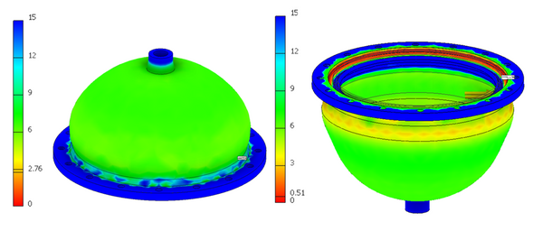
Figure 18. Safety Factor of Liquefaction Tank components

Figure 19. Illustration of Liquefaction Tank
The final and essential component of the liquefaction tank is the filter bed, which is responsible for removing small rock fragments and impurities. As shown in Figure 12, the filter bed employs a two-step filtration process: (1) charcoal filtration and (2) steel mesh filtration.
The filter bed holder, which houses the filter materials, was designed as illustrated in Figure 20. ABS was selected as the holder material due to its superior machinability. Figure 21 presents a cross-section of the liquefaction tank with the filter bed holder mounted, while Figure 22 shows the machined components of the liquefaction tank. Figure 23 illustrates the filter bed holder filled with filter materials, and Figure 24 depicts the fully assembled liquefaction tank.

Figure 20. Filter bed holder

Figure 21. Cross section of the liquefaction tank with filter bed holder mounted

(a)

(b)
Figure 22. machined components of the liquefaction tank

Figure 23. Filter bed holder with filter material filled in

Figure 24. Assembled liquefaction tank
3.3 Heating Tank
The heating tank is where the final step of propellant processing occurs, converting liquid carbon dioxide into its supercritical state. Due to the extremely high internal pressure requirements, a commercial Composite Overwrapped Pressure Vessel (COPV) tank was selected for ease of use. Acecare's 3L scuba diving tank, shown in Figure 26, was chosen for this purpose.
By referencing the carbon dioxide density and phase diagram in Figure 25, it was determined that heating the carbon dioxide to 40°C is necessary to transition all liquid carbon dioxide into the supercritical state. A commercial thermostat was used to heat the COPV tank. As shown in Figure 28, a heating coil wraps around the COPV tank to provide the required heat.

Figure 26. COPV

Figure 27. Density & Phase diagram of carbo dioxide [12]

Figure 28. Heating tank mounted on the Hopper
The inlet thread of the COPV tank is an M18x1.5 type thread, which is uncommon compared to standard thread types such as PT or NPT. To address this, a custom adaptor for the heating tank was designed and fabricated, as shown in Figure 29. The adaptor features a male M18x1.5 thread and a male 1/2-inch tube connection. Figure 30 illustrates the adaptor with an O-ring fitted, and Figure 31 shows the heating tank with the adaptor installed
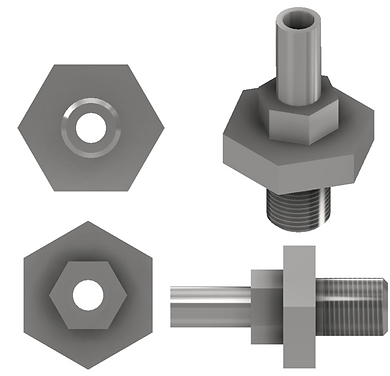
Figure 29. Adaptor design


Figure 30. Heating Tank Adapter

Figure 31.
The supporting hardware for the heating tank was designed and fabricated, as shown in Figure 32. The support structure was engineered to securely hold the tank and withstand intense vibrations during testing. A hexagonal hole, slightly larger than the adaptor's hexagonal shape, was incorporated at the center of the support to prevent circumferential movement of the tank.

Figure 32 Heating tank supporter
3.4 Harvesting Robot Arm & Hand
The harvesting system is responsible for collecting raw solid carbon dioxide. It includes a pair of grinding and scooping hands, along with a robotic arm for lifting and transferring the ice. Since the propellant is in a solid state, a grinding mechanism was implemented to minimize energy consumption. The grinding and scooping hands, powered by a single servo motor, grind the surface and collect fragments. The collected fragments are then lifted 70 cm by a servo-actuated robotic arm and transferred to the liquefaction tank.
The components of the grinding and scooping hands were designed and fabricated, as shown in Figure 33. ABS plastic was chosen as the material for its durability and machinability. Two servo motors, shown in Figure 34, are used to change the hand’s direction and actuate the claws. A gear mechanism was designed to allow both claws to be actuated by a single servo motor. Figure 35 shows the fully assembled harvesting hand.

(a)


(b)
Figure 33. Harvesting hand components

Figure 34. Servo motor

Figure 35. Assembled harvesting hand
The robotic arm is responsible for transferring harvested ice propellant to the liquefaction tank. It features four joints, enabling movement along the x, y, and z axis. The arm is composed of eight ABS components. Figure 36 shows the individual components of the robotic arm, Figure 37 depicts the assembled arm integrated with the harvesting hand, and Figure 38 illustrates the robotic arm and hand fully integrated with the Hopper.

(a)

(b)

(c)

(d)

(e)
Figure 36. Robot arm components

Figure 37. Assembled Harvesting robot arm and hand

Figure 38. Harvesting robot arm integrated with APHH
3.5 Frame
The Hopper’s frame is designed to support all subsystems and components of the APHH in both flight and steady conditions. While minimizing weight, the frame must be robust enough to withstand vibrations and stresses under extreme conditions. The frame consists of six legs and a main body. ABS plastic was chosen for the main body, while Nylon was selected for the legs. This design ensures uniform weight distribution and effectively handles the forces exerted by the four cold gas thrusters, located at each corner of the rectangular main body.
The frame is designed to accommodate the liquefaction tank, heating tank, and four cold gas thrusters. Figure 39 illustrates the frame's geometry. Von Mises stress analysis was performed to validate the frame's reliability. Figure 40 displays the safety factor distribution: (a) for steady conditions and (b) for in-flight conditions. Figures 41 and 42 show the design of the frame’s main body, while Figure 43 illustrates the frame’s legs.

Figure 39. Illustration of APHH frame
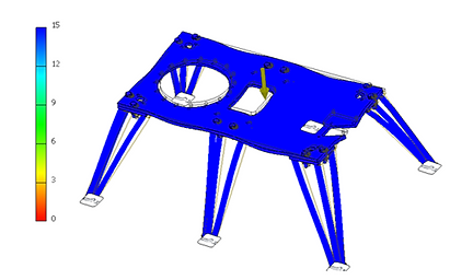

Figure 40. Stress analysis of APHH frame

Figure 42. Frame main body

Figure 43. Frame leg
3.6 Valve
The fine manipulation of flow is required to control the thrust of APHH. Therefore, main fuel valve or MFV for APHH was designed and built. The servo actuated ball valve concept was selected for the design for its controllability and simplicity. The valve consists of 3 parts: Servo motor holder, Ball-valve holder, and The adaptor that connects the handle of the ball valve and the servo motor’s arm. Figure servo motor shown in Figure 44 and components of the valve is shown in Figure 45. Figure 46 shows the assembled MFV.

Figure 44. Servo motor

(a)

(b)

(c)
Figure 45. MFV components

Figure 46. MFV
3.7 Assembly
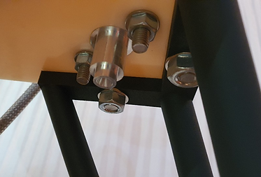
Swagelok, NPT, and PT fittings were used to connect and assemble the fuel lines of the APHH. Figure 47 shows the inlet line of the liquefaction tank, while Figure 48 illustrates the inlet and outlet lines of the heating tank. Figure 49 depicts the cold gas thruster integrated into the APHH, and Figure 50 highlights the propellant distribution section. Figure 51 shows the inlet line leading to the heating tank, and Figure 52 presents the fully assembled APHH.

Figure 47. Liquefaction tank inlet line
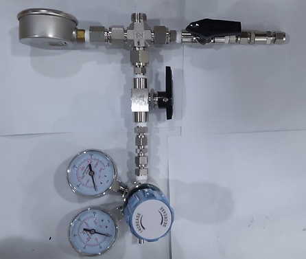
Figure 48. Heating tank Inlet & Outlet line

(a)
(b)
Figure 49. Cold Gas thruster mounted

Figure 50.
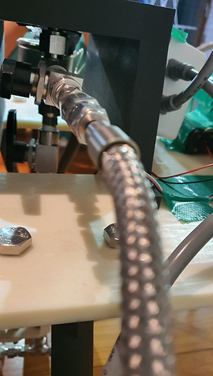
Figure 51. Heating tank inlet view

(a)

(b)
Figure 52. APHH
4.Testing
4.1 Wet Dress Rehearsal
A WDR was conducted to validate the performance of the liquefaction tank. Two kilograms of dry ice were loaded into the tank, and the system was monitored until the pressure exceeded 50 bar. The liquefaction tank performed as expected, maintaining the pressure for three hours without deformation or bursting. Figure 53 shows a photograph taken during the cryogenic test.
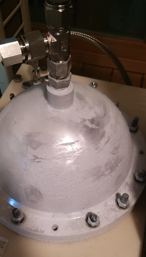
Figure 53. Cryogenic testing
4.2 Static Fire
The APHH was tested on January 1, 2022. The harvesting system, liquefaction system, and cold gas propulsion system functioned as expected. However, the harvesting system was removed during the firing test to prevent damage from the intense vibrations of the cold gas thrusters. Due to the cold weather, the APHH was unable to generate supercritical carbon dioxide, resulting in insufficient thrust to lift the hopper. Figure 54 shows the APHH with one cold gas thruster producing thrust.

Figure 54. Static fire testing
5.Conclusion
5.1 Conclusion
In future research, the flight time of the APHH will be tripled by reducing the weight of its hardware components, including the frame, tanks, and propulsion system. This will involve the use of lightweight, high-strength materials and optimized structural designs to minimize mass without compromising durability. Additionally, four independently controlled valves will be integrated to adjust the thrust of each cold gas thruster. This modification will allow for precise attitude control and improve flight safety, addressing a key limitation identified during this study.
The current APHH has a noticeably short flight duration, primarily because it was designed to operate in Earth's gravity, where the required thrust-to-weight ratio significantly limits performance. However, in environments with lower gravity, such as the polar regions of Mars, the APHH’s flight time is projected to increase to approximately 50 seconds. This improvement is due to the reduced gravitational force, allowing for more efficient use of the propellant and extended operational duration.
Furthermore, if tested on Europa, where gravity is even weaker than on Mars, the flight time could extend to three minutes. This capability would dramatically increase the hopper’s range and exploration potential, enabling it to survey larger areas and reach regions inaccessible to traditional rovers. Such advancements would significantly enhance the APHH’s applicability for extraterrestrial exploration missions in icy or low-gravity environments.
REFERENCE
[1] Huzel, Dieter K. Modern engineering for design of liquid-propellant rocket engines. Vol. 147. AiAA, 1992.
[2] Sutton, George P., and Oscar Biblarz. Rocket propulsion elements. John Wiley & Sons, 2016.
[3] Tummala, Akshay Reddy, and Atri Dutta. "An overview of cube-satellite propulsion technologies and trends." Aerospace 4.4 (2017): 58.
[4] Nguyen, Hugo, Johan Köhler, and Lars Stenmark. "The merits of cold gas micropropulsion in state-of-the-art space missions." The 53rd International Astronautical Congress, IAC 02-S. 2.07, Houston, Texas. 2002.
[5] https://en.wikipedia.org/wiki/Carbon_dioxide_(data_page)
[6] Anis, A. Cold Gas Propulsion System–An Ideal Choice for Remote Sensing Small Satellites. In Remote Sensing–Advanced Techniques and Platforms; Escalante-Ramirez, B., Ed.; IntechOpen: London, UK, 2012.
[7] Zumdahl, Steven S., Susan A. Zumdahl, and Donald J. DeCoste. Chemistry. Cengage Learning, 2016.
[8] . Gibbon, D. A Review of the use of butane as a low cost propellant. In Proceedings of the 2010 Space Propulsion, San Sebastian, Spain, 3–6 May 2010; p. 11.
[9] Turner, M.J. Rocket and Spacecraft Propulsion, 2nd ed.; Springer: Chichester, UK, 2006
[10] Braeunig, R. A., “Rocket Propulsion,” Rocket & Space Technology, retrieved 25 April 2020
[11] Jiang, Hao, Athanassios Z. Panagiotopoulos, and Ioannis G. Economou. "Modeling of CO2 solubility in single and mixed electrolyte solutions using statistical associating fluid theory." Geochimica et Cosmochimica Acta 176 (2016): 185-197
[12] https://www.iso.org/obp/ui/#iso:std:64147:en
[13] Nothnagel, Sarah Lynn. Development of a cold gas propulsion system for the talaris hopper. Diss. Massachusetts Institute of Technology, 2011.